Maximizing Accuracy with a Load Cell for Rocket Engine Thrust Measurement
- Sep 10, 2025
- 4 min read
When you push a propulsion system to its limits, small errors add up fast. Accurate thrust data drives injector tuning, turbo machinery health, and structural margins. Programs across space and defense rely on MSNST - Measurement Specialists Inc., dba National Scale Technology - for precision force measurement designed, machined, and calibrated in-house in Huntsville, Alabama.
Since 1982, MSNST has helped teams measure forces from a few grams to multi-million lbf with standard and custom load cells built to spec. Our work spans NASA’s SLS/Artemis and Orion programs as well as defense applications where measurement integrity is mission-critical. If your next hot-fire demands uncompromising data, our engineers can design a load cell for rocket engine thrust measurement matched to your stand geometry, thrust range, environment, and DAQ - backed by ISO 9001:2015 quality and FM Approvals. AS9100 approval is pending.
The Role of Load Cells in Rocket Engine Thrust Measurement
A strain-gauge load cell converts mechanical force into an electrical signal by measuring elastic deformation of a precision metal element. The strain gauges are wired into a Wheatstone bridge. When the element is loaded, the subsequent change in resistance across the Wheatstone bridge is measured; the change in resistance is directly proportional to the force applied.
In high-force propulsion testing, 4340 high strength alloy or stainless constructions deliver the stability, accuracy, and ruggedness needed for static and dynamic events.
Common Configurations:
Inline tension/compression between the engine frame and the fixed structure for pure axial thrust.
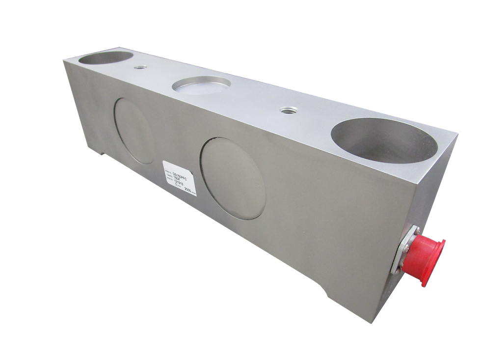
Cantilever/beam elements where inline placement isn’t feasible.
Reaction-based low-profile (“pancake”) cells beneath thrust take-out fixtures for high stiffness and low height.
Load cells are standard in propulsion testing because they offer predictable linearity and repeatability, strong signal-to-noise at full scale, broad capacity coverage, and packaging that can fit into an existing tight test stand or new application, and tolerate harsh environments. At MSNST, we help determine what capacity and configuration will work in the application and will custom build to meet your specific needs. When re-instrumenting an existing test stand, we can replace obsolete units where the original manufacturer is out of business or may no longer support the product. MSNST’s engineering team are also able to offer expert advice on change outs and installation. Drop in replacements or specialized units are made per your requirements.
Key Factors That Affect Thrust Measurement Accuracy
Environmental Conditions
Thermal gradients (cryo lines, radiant heat), vibration, EMI/RFI, and residue exposure can shift zero and span. MSNST builds for extreme temperature conditions and temperature fluctuations. - including high-temperature constructions (≈400 °F /200 C operating, ≈550 °F/290 C survivability) - and can add sealing and shielding to stabilize the signal. MSNST has built load cells that were integrated into satellites and subject to sub-zero temperatures as well as vibratory and C4 explosive tests to simulate atmospheric re-entry conditions.
Mechanical Integration
Alignment, fixture stiffness, and clean load paths limit off-axis and parasitic forces. MSNST’s mounting guidance and in-house machining help minimize moment arms and friction so the sensor “sees” true axial thrust.
Signal Quality
Grounding, excitation, connectorization, and cable routing drive noise performance. Options like dual bridges and application-specific connectors simplify integration and improve redundancy.
Load Cell Design and Calibration
Element geometry, gauge patterning, temperature compensation, and NIST-traceable calibration all affect accuracy. MSNST calibrates from 1 gram to 1,600,000 lbf, and supports practical recalibration intervals. Regularly scheduled calibrations provide maximum performance confidence.
Load Cell Features That Maximize Accuracy
Materials & geometry: High-strength stainless/alloy steels with stiff, symmetric designs reduce creep and bending sensitivity while preserving bandwidth for dynamic events.
Hermetic sealing & ingress protection: Guards against humidity, thermal cycling, and propellant residue for long-term stability.
Thermal compensation: Multi-gauge patterns and matched resistors keep zero and span stable as the stand heats and cools.
Overload & fatigue protection: Mechanical stops and conservative strength ratios survive ignition spikes and shock.
Dual-bridge outputs: Redundancy for cross-checks or DAQ/telemetry splits in mission-critical testing.
Custom connectorization & cabling: Application-specific assemblies reduce noise and speed setup.
Bottom line: for accuracy under real test-cell conditions, MSNST’s custom load cells are engineered around your interfaces, environment, and acceptance criteria.
Choosing the Right Load Cell for Rocket Thrust Applications
Selecting the optimal sensor starts with the physics of your stand and the realities of your test plan:
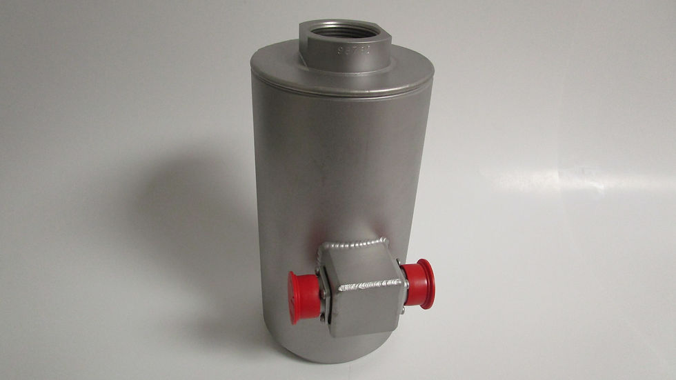
Load direction & interfaces: Axial tension, compression, or bi-directional? Inline canisters and S-types excel in direct axial paths; low-profile/pancake cells are best suited for reaction mounts where height is constrained. Annular ("donut") cells can capture through-bolt clamping or sling loads in unique fixtures.
Expected thrust range & dynamics: From sub-scale thrusters to million-pound-class engines, pick a capacity that centers your operating force for best resolution while preserving headroom for transients. MSNST covers capacities from hundreds of pounds to multi-million-lbf classes and designs even higher as needed.
Environment: Cryogenic plumbing nearby? High radiant heat? EMI-dense test cells? Specify sealing, thermal treatments, and cable/connector details accordingly.
Space constraints & maintenance: If you need minimal stack height and easy swap-outs, low-profile cells simplify integration; if you need robust overload capability with simple axial alignment, canisters are the best option.
When application requirements remain unclear, MSNST's engineering team can evaluate your test stand configuration and thrust envelope to recommend a purpose-built load cell for rocket engine thrust measurement that meets your accuracy targets, testing cadence, and budget constraints. Our collaborative approach ensures optimal sensor selection for your specific propulsion testing requirements.
Best Practices for Maximizing Load Cell Accuracy
Proper Installation & Alignment
Use rigid, flat surfaces; align the loading axis; avoid side-loads and torsion. MSNST’s Mounting guidance and precision adapters preserve sensor accuracy.
Regular Calibration Schedules
Set intervals to match test frequency and severity. MSNST provides NIST-traceable calibration (1 g to 1,600,000 lbf) with expedited options. Regularly scheduled calibrations are recommended for maximum performance confidence.
Environmental Shielding
Add thermal barriers, proper grounding, cable shielding, and strain relief. High-temperature and hermetic builds protect signal quality in hot-fire cells.
Data Acquisition Best Practices
Match excitation to bridge resistance and cable length; sample above event bandwidth; log redundant channels with dual bridges. MSNST can tailor bridge configuration and connectors to your DAQ.
Conclusion
High-fidelity thrust measurement data remains non-negotiable for successful propulsion system development and qualification programs. With ISO 9001:2015 quality, FM Approvals, deep space-test experience, and full in-house design, machining, and calibration, MSNST delivers the load cell for rocket engine thrust measurement you can trust. Plan your next firing sequence with the team that designs custom load cells around your constraints - and documents performance for QA.
Contact us to request a quote or call (800) 264-9990. Submit before 12:00 PM CST for a same-day response; after noon, you’ll hear back the next morning.


Comments